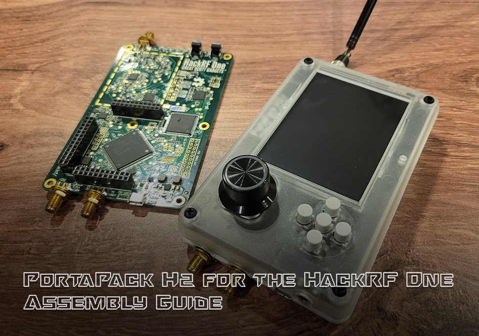
In this article we will be walking through the assembly of the HackRF PortaPack H2 from Hacker Warehouse. The PortaPack is an add-on board for Great Scott Gadget’s HackRF One that gives the device an onboard GUI and suite of SDR functionality without needing to connect to a workstation. Before using the device, you will need to flash the desired PortaPack firmware to the HackRF.
Components
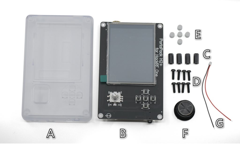
| PortaPack H2 Components | |||
|---|---|---|---|
| A | Clear acrylic enclosure (1) | E | Button caps (5) |
| B | PortaPack H2 board (1) | F | Dial knob (1) |
| C | Board standoffs (4) | G | Optional internal speaker cable (1) |
| D | Enclosure screws (8) | ||
Ensure that all of the components are present before beginning assembly. In addition to the items listed above, you will also need your HackRF One board, a screw driver, and a clean surface for handling the bare circuit boards. Note that the device does not come with an internal speaker, but a cable is provided for those that wish to add this feature to the device.
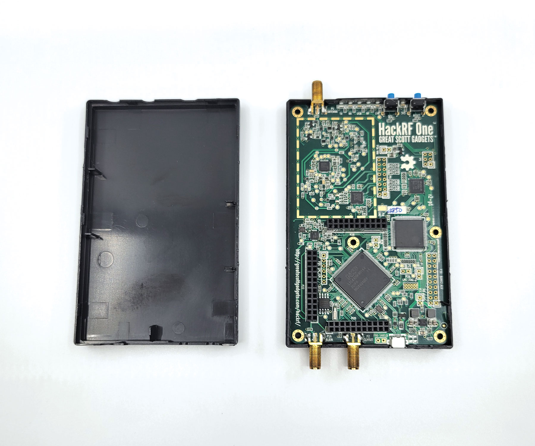
Disassembling the HackRF One
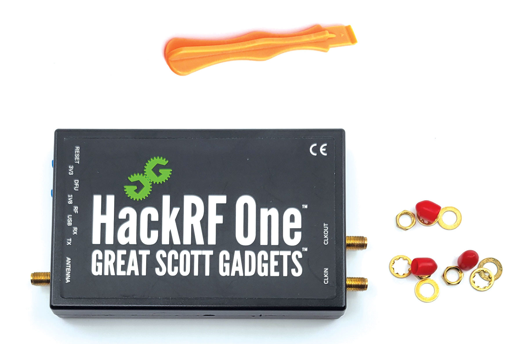
Gather your HackRF and a plastic pry tool to remove the enclosure before assembling the PortaPack. Remove the red covers and fasteners from the SMA connectors and set aside for later.
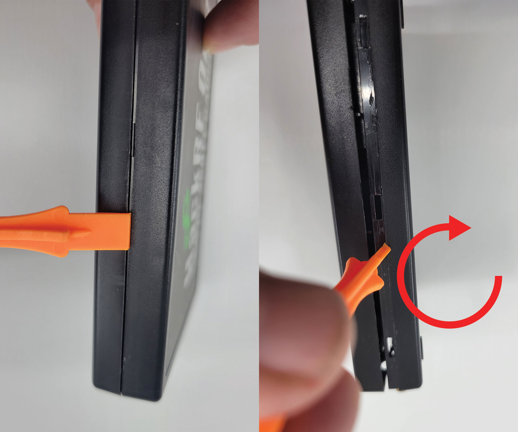
The plastic enclosure of the HackRF One consists of a top and bottom half that snap together around the outside of the board. Use the wedge tool-tip of the pry bar to get into the seam between the two halves. With the tool-tip in place, rotate the pry bar like a screw driver to separate the top from the bottom. Work the pry bar along the seam until the two halves snap apart. With the enclosure open, carefully remove the HackRF board from the bottom half and set aside for use in assembling the PortaPack.
Assembling the PortaPack
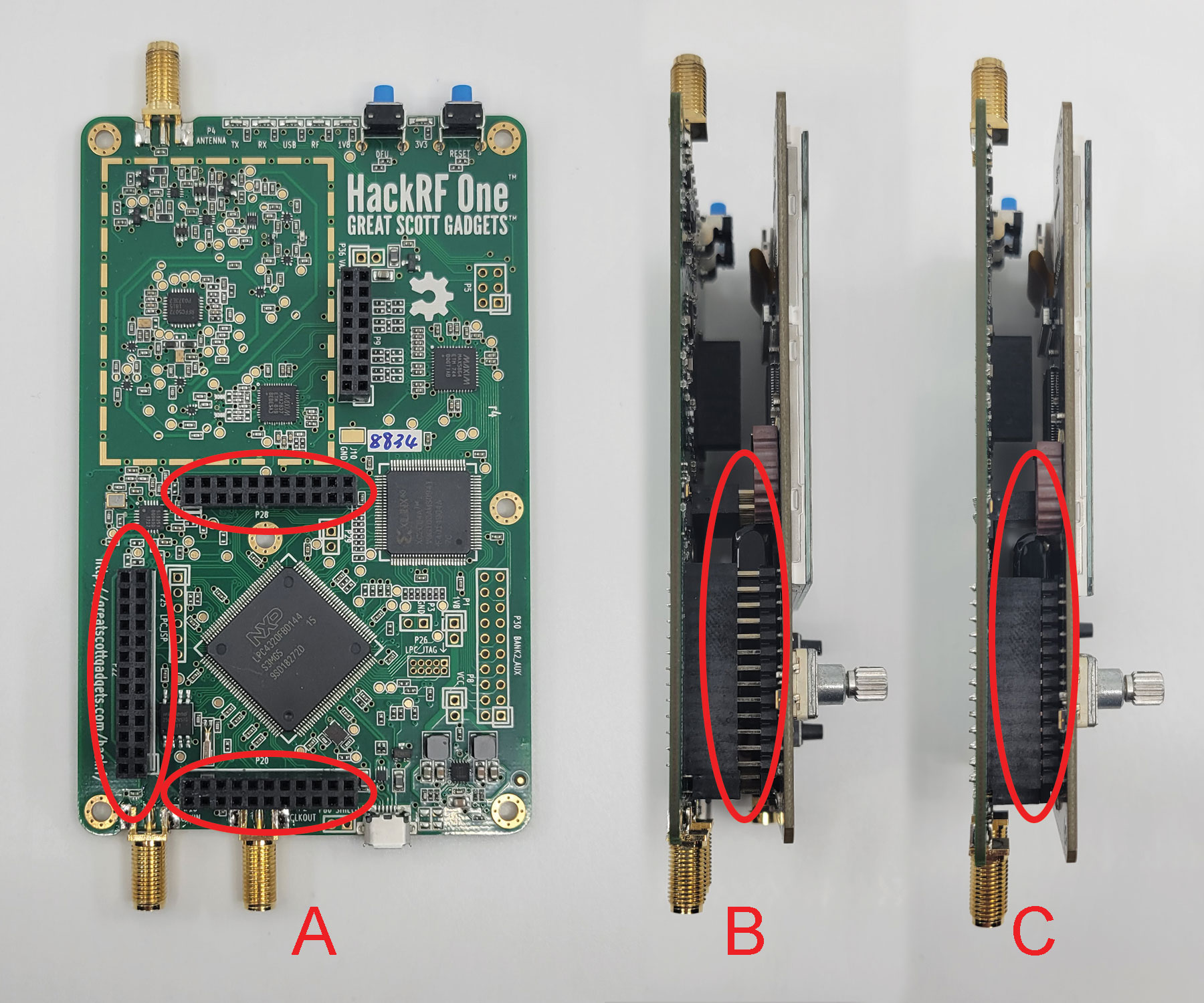
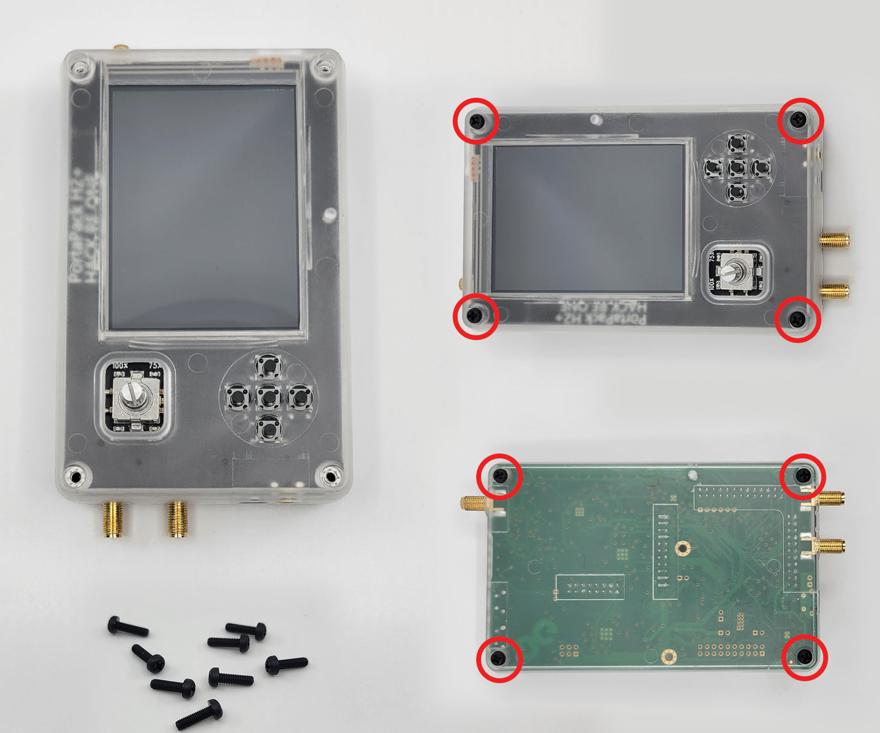
Locate the three sets of expansion headers on the HackRF board that correspond to those of the PortaPack H2. As seen in the figure above, these can found on the lower left corner of the HackRF. Carefully align the pins and use gentle pressure to fully mount the boards.
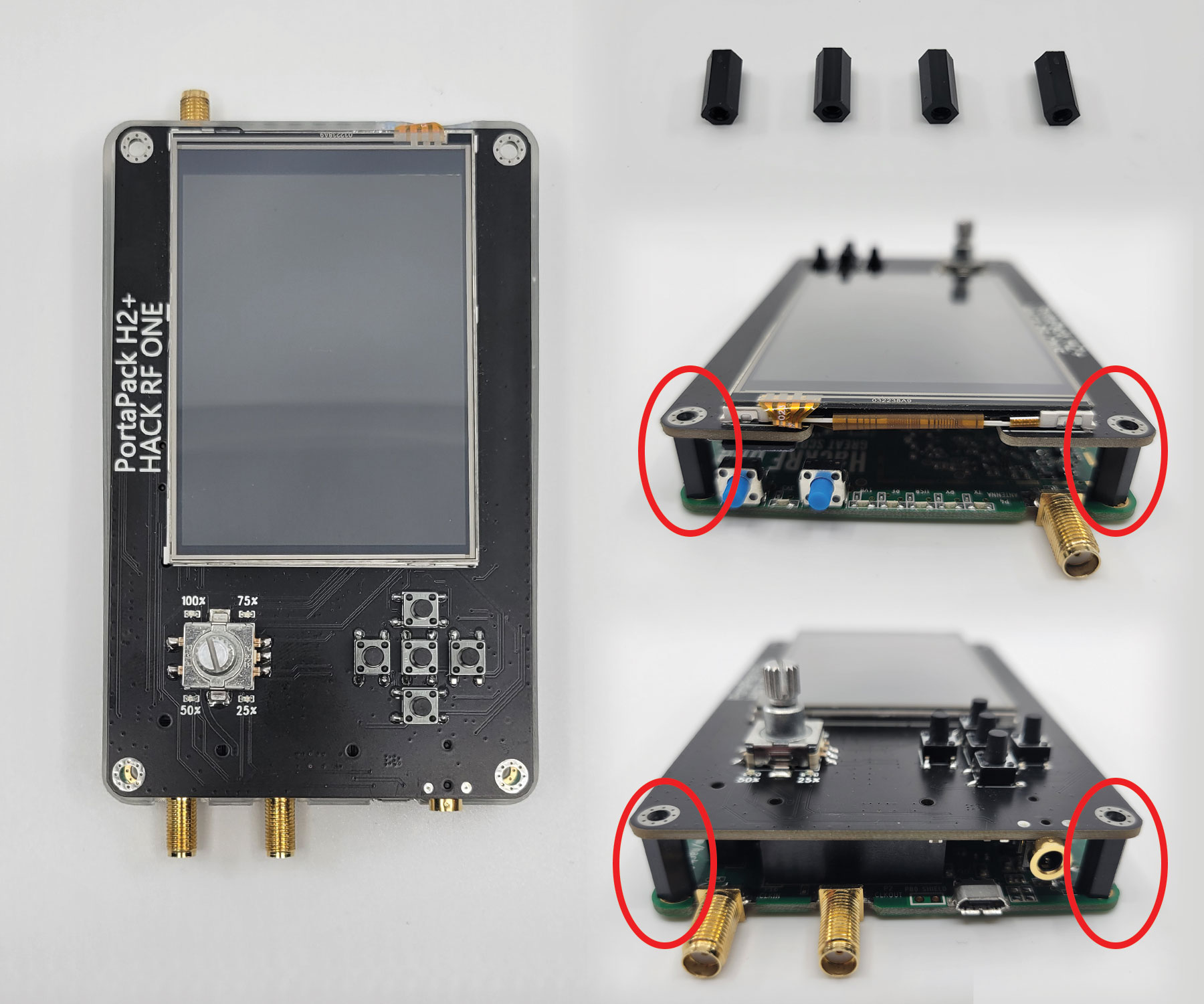
With the board assembly complete, grab the four included board standoffs and position them between the boards, aligning with the holes in each corner. The fit should be snug and friction alone is enough to keep them in place until while adding the enclosure.
Take the lower half of the acrylic enclosure and make sure that the cutouts for the antenna and clock are on the left-hand side and the opening facing up. Lower the board assembly into enclosure with PortaPack H2 facing up and align the antennas and buttons with the corresponding cutouts. Press down to snap the board assembly into place. Take the top half of the enclosure and lower it onto the board assembly with screen, button, and antenna cutouts aligned and snap it into place.
Use the eight screws to secure the case to the board assembly via the holes aligning with the standoffs in each corner. The screws will thread into the standoffs and clamp the enclosure together when tightened.
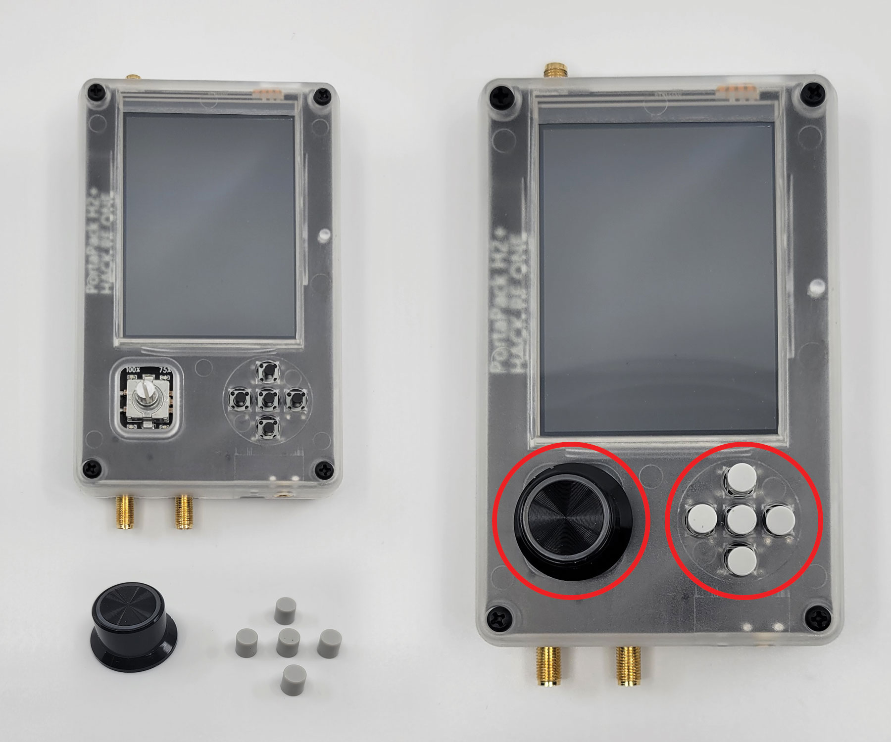
Finally, place the black plastic knob on the dial below the screen and press it gently until it locks into position. Put the five button caps over the buttons the right of the dial. You may accidentally power the device on in this process, which is not a problem. If the device boots up, just turn it off by pressing the dial down twice in rapid succession.
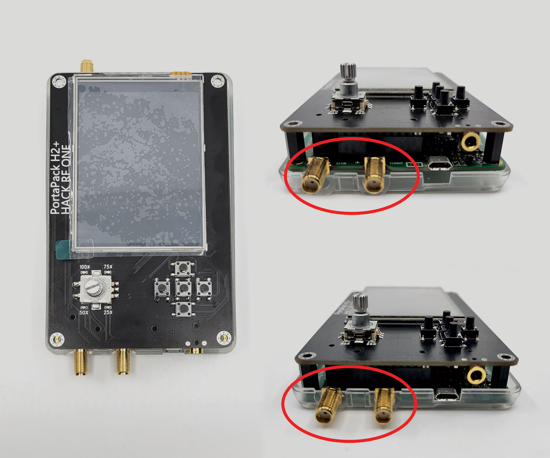
Device Features
| PortaPack H2 Features | |||
|---|---|---|---|
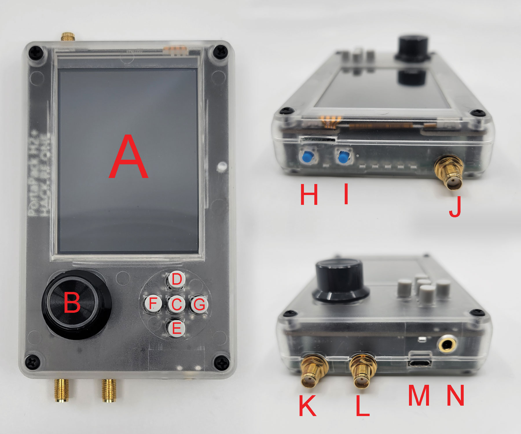
| A | GUI Screen (2.25 x 3 inch color LCD) | H | Reset Button |
| B | GUI Dial | I | DFU Button |
| C | GUI Select Button | J | SMA Antenna In |
| D | GUI Up Button | K | SMA Clock In |
| E | GUI Down Button | L | SMA Clock Out |
| F | GUI Left Button | M | USB Mini Port |
| G | GUI Right Button | N | Audio Out |
Before you can start using the PortaPack, you will need to flash the appropriate firmware to the HackRF – the device will power on with a black screen otherwise. Please refer to our guide to flashing the Mayhem firmware for detailed instructions on this procedure.
This concludes our assembly guide for the PortaPack H2 – stay tuned for tradecraft techniques on using the device for RF research in the field. If you haven’t picked up a HackRF One or PortaPack H2, make sure to visit HackerWarehouse. Until next time, keep it between the laws and keep it between the LOLs.